Crossflow Cooling Tower
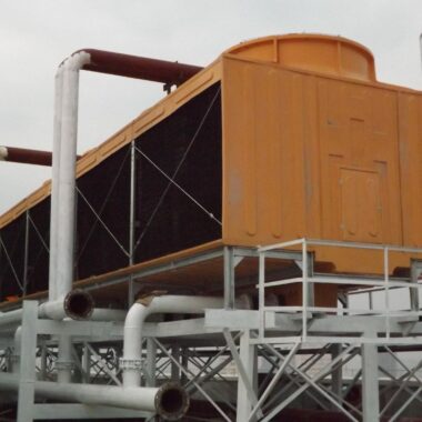
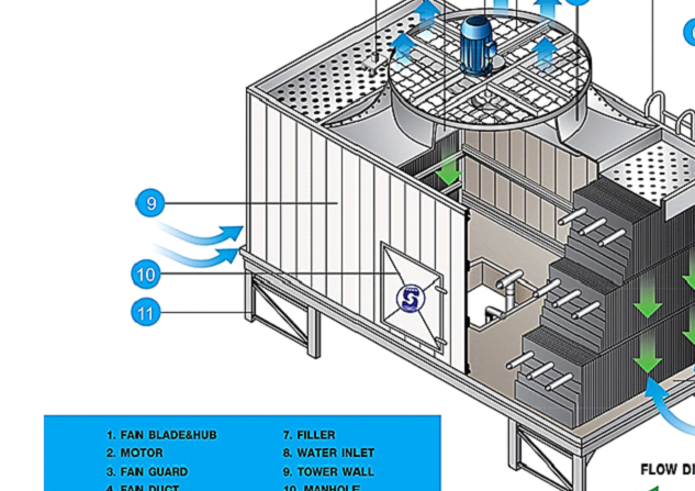
Crossflow Cooling Tower, Hot water is delivered from outside to hot water basin located two sides on the top of the tower. Then it will be distributed over pvc fillers which are installed underneath the basins. Cool air is sucked by fan on top of the tower through fillers from the side. Heat transfer will take place between hot water and cool air. Cooled water will fall down to cool water basin before being sucked back for again cooling application. Hot air will be released to outside. Benefit of this type of cooling tower is less air pressure loss. Fan will consume less absorbed horse power.

More Images of Crossflow Cooling Tower
Material of Construction
| PART | MATERIAL |
|---|---|
| STRUCTURE | Made of hot dip galvanized steel. All parts are connected with galvanized bolts & nuts. Tower side walls are made of glass fiber reinforced plastic. Service door is provided for inside maintenance conveniently of Crossflow Cooling Tower |
| AIR INLET MESH | Made of ABS plastic to prevent big foreign materials from being sucked into the tower and to eliminate splashing of water to outside. |
| FAN DUCT | Made of fiberglass reinforced plastic. Shape is cylinder and slightly tapered to enhance aerodynamic efficiency and reduce pressure loss. |
| MOTOR | Motor is to drive the tower fan. Due to the humid air stream, the motor has to be water and moisture-proof type IP 55 rated motor. Higher ratings may be required. |
| GEAR REDUCER | Requires high airflow, necessitating a big fan blade and diameter. The fan runs at lower speed to reduce tip speed and noise. Gear reducer or V-belt pulley drive are options available. Gear reducer offers longer life and less maintenance, but is noisier than V-belt drive. |
| FAN | Made of aluminum alloy. Creates airflow for effective water and air contact. An axial flow fan is suitable for high airflow. It must be high efficiency, low vibration, corrosion-resistant, and safely operated. |
| MOTOR SUPPORT | Made of hot dip galvanized steel. Supports the motor and gear reducer securely. Installed on top of the fan duct with a fan guard to prevent danger of fan contact. |
| HOT WATER BASIN | Made of fiberglass reinforced plastic. Receives hot water from outside. Nozzles are installed at the bottom to distribute hot water over the underneath fillers. |
| FILLER | Made of PVC plastic film and corrugated. Water spreads over the filler, creating a thin film that enhances heat transfer between water and air stream. |
| COOL WATER BASIN | Made of fiberglass reinforced plastic. Receives cooled water from the bottom of the filler. Must have sufficient volume to maintain water level during operation. |
Salient Features
- Easy maintenance by design.
- No elaborate pillar foundations required; can be placed on any flat surface.
- All structural components in HDG Steel; SS 304 and SS 316 available upon request.
- Adjustable pitch axial flow fans made of dynamically balanced aluminum.
- Casings made of FRP (Fibre Reinforced Plastics) for durability and strength.
- All joints fastened with SS 304 fasteners.
- Uniform water dispersion achieved through flower pot target nozzles.
- Lighter operational weights reduce space requirements.
- Future expansion achievable with adaptations to existing towers.
- Multi-cell design accommodates seasonal cooling needs.
- Low pumping head.
- Lower first cost for pumping systems.
- Lower annual energy consumption and operating costs.
- Accepts larger variations in water flow without adversely affecting the tower distribution pattern.
- Easy maintenance access to distribution nozzles.
- Low static pressure drop.
- Reduced drift.
- Reduced recirculation.
- More air per fan horsepower.
- Lower energy and operating costs.
Application of Crossflow Cooling Tower
- Hospitals
- Malls
- Theaters
- Air-conditioned halls
- A/C plants and cold rooms
- Chemical industries
- Dairy, citrus, and other food processing industries
- Distilleries and breweries
- Industries with heat processes
- Oil refineries
Advantages
- Low pumping head, resulting in lower operational costs.
- Accepts variations in water flow without changing the distribution system.
- Easy maintenance access to vital parts.
- Reduced drift loss due to the absence of water droplets.
- Lower noise levels due to the absence of water noise.

