Introduction
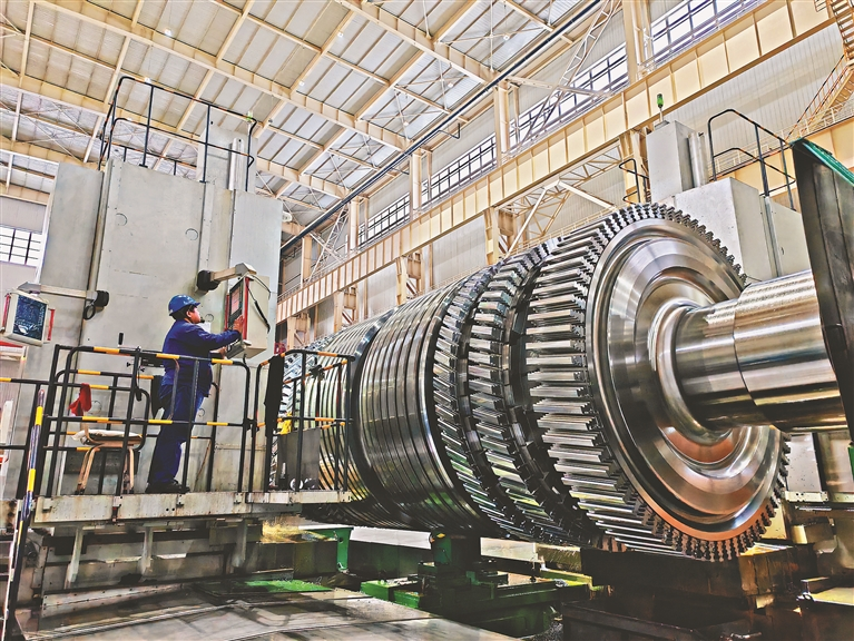
Turbine lubrication cooling are critical machines that convert energy from fluids like steam, gas, or water—into mechanical motion or electrical power. These machines are engineered for efficiency and high performance, often rotating at speeds exceeding 3000 to 3600 RPM under intense thermal and mechanical loads. With such operational intensity, managing friction, wear, and thermal stress becomes vital.
The lubrication system in a turbine performs two interrelated functions:
- Lubrication – Prevents metal-to-metal contact by forming an oil film, reducing friction and wear.
- Cooling – Dissipates the heat generated from moving parts such as journal bearings, thrust bearings, and gear couplings.
The oil used in this system becomes a heat transfer fluid, absorbing the excessive heat and transporting it away from the critical components to a cooling unit, ensuring safe and efficient turbine operation. Failure in either aspect—lubrication or cooling—can lead to overheating, mechanical seizure, catastrophic damage, or complete turbine failure.
Need for Turbine Lubrication Cooling:
- Extreme Mechanical Stress: Bearings and gears in turbines endure high stress under fluctuating load and speed. The absence of proper lubrication and heat dissipation may cause deformation, scoring, or even total failure.
- Oil Degradation Risk: Prolonged exposure to elevated temperatures leads to chemical breakdown of oil, producing acidic compounds, sludge, and varnish. This compromises lubrication and clogs narrow passages.
- Hydrodynamic Lubrication Failure: Turbines rely on full-film lubrication, where a stable oil film separates moving surfaces. Rising oil temperature decreases viscosity, reducing film thickness, leading to boundary lubrication or even metal contact.
- Component Misalignment and Thermal Expansion: Uncontrolled temperature increase can cause expansion of shafts and casings, disturbing critical clearances and causing vibrations or rubbing.
Advanced Working Principles:
The turbine lubrication cooling system is a dynamic and highly monitored process. Here’s how it works in further detail:
- Pumping Stage: A dedicated main oil pump, often driven mechanically or electrically, pressurizes the lubricating oil, distributing it to various parts of the turbine. In some systems, an emergency oil pump and AC/DC backup pumps are provided for redundancy.
- Bearing Cooling: The oil enters journal and thrust bearings through narrow passages. As the bearings rotate, frictional heat is transferred into the oil. The heat transfer is enhanced by the shear rate and surface contact between the oil and the bearing.
- Heat Extraction via Heat Exchanger: The oil is routed to a cooling unit, usually a shell and tube heat exchanger, where it is cooled by a counterflow of water or air. Cooling efficiency depends on:
- Heat exchanger surface area
- Flow rates of both oil and coolant
- Temperature differential
- Fouling factors on exchanger surfaces
- Temperature Regulation & Bypass Mechanisms: Sophisticated systems incorporate thermostatic bypass valves, which route oil around the cooler if it’s already within the desired temperature range, improving efficiency and preventing overcooling.
- Oil Conditioning Loop: Often includes a degassing chamber, centrifugal separators, or vacuum dehydrators to remove entrained air, water, and particulates that could degrade lubrication performance.
Extended Types of Cooling Methods:
Forced Water Cooling:
- Common in steam turbine plants.
- Involves high flow rates of treated water (demineralized) through shell and tube coolers.
- Needs strict water chemistry control to prevent fouling and corrosion.
Air Blast Cooling:
- Used where water supply is unavailable or where portability is key (e.g., wind turbines).
- Employs axial fans blowing across finned tube banks.
- Suitable for smaller or mobile turbines.
Hybrid Cooling Systems:
- Combine both air and water systems for flexibility.
- May include closed-loop glycol systems for arctic or hot desert environments.
Key Components
Main Oil Pump:
- Delivers required pressure (3 to 6 bar) and flow (50 to 500 LPM depending on turbine size).
- May be gear type, screw type, or centrifugal.
Reservoir or Sump:
- Capacity must ensure at least 5–10 minutes of full-load operation in the event of pump failure.
- Incorporates baffles to aid de-aeration and sludge separation.
Heat Exchangers:
- Shell and Tube: Best for large turbines; highly durable and easy to service.
- Plate Heat Exchanger: Compact, high-efficiency, ideal for modular turbine skids.
- Air-cooled Cooler: With fan units; suited for isolated or arid environments.
Filtration Unit:
- Primary and secondary filters are often used in parallel for uninterrupted operation.
- Bypass valves protect against clogging.
Conclusion
Turbine lubrication cooling systems are more than auxiliary subsystems they are integral to the turbine’s operational integrity and reliability. From massive power plants to offshore wind farms, the cooling of lubricating oil dictates not only the turbine’s performance and uptime, but also its safety, energy efficiency, and lifecycle cost. The evolution of turbine technology is continuously demanding greater thermal loads, tighter tolerances, and longer operational periods. This places increasing emphasis on lubrication cooling solutions that are smarter, more robust, and more sustainable.